Sequence Diagram
|
Sequence diagrams show interactions between objects. These interactions are modeled as messages. Sequence diagrams have many purposes:
Because sequence diagrams show event flow for a given scenario, the scenario MUST BE understood by the designer. For novice designers, it is generally easier to create sequence diagrams from a scenario which is written in narrative form. When novice designers attempt to create sequence diagrams from point-form scenarios they tend to miss important objects and the objects that are identified tend to be incohesive. In this document, a series of scenarios will be presented for the following Use Case:
Figure 1: Use Case Diagram
An appropriate sequence diagram will be shown for each scenario Note: These notes show one method of creating sequence diagrams which fits very well well with the Gartner 3-layer model (with emphasis on the application layer). GUI objects are NOT included in these sequence diagrams. Some textbooks will include GUI objects as part of the sequence diagram. THIS IS NOT RECOMMENDED because the purpose of Use Cases and scenarios is to describe Application logic. By introducing presentation layer components into sequence diagrams, the designer will inevitably couple the application layer with the presentation layer. |
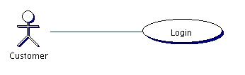
Figure 2: Sequence Diagram: Successful login In this first example, you will see quite clearly the application objects (:LoginController and :UserManager) as well as the domain objects (JimsAccount:Customer and :Session). You should also note that the LoginController is not doing any real work; it is delegating the responsibility of handling the request to another object. Similarly, the UserManager object is remaining cohesive by managing the user objects (in this case, the users are Customers). The UserManager is finding the appropriate Customer object and then forwarding the request to that object. Again, notice that the UserManager is not doing the work of the request; it is delegating the real work (ie. the work of the domain objects) to the domain objects. When creating sequence diagrams, the first object (it one with which the actor directly interacts) MUST ALWAYS be a controller object. Actors do not interact with domain objects directly. Actors interact with an application. The application provides a high-level interface and maps user request to actions that are understandable by the domain objects. By developing applictions in this manner, the presentation layer can be replaced with any implementation, but the essence of the application (what the applicaton does) does not change. You will also note that the sequence diagram also shows the same information which is contained within the scenario. The only difference is that the sequence diagram is in diagram form where the scenario is in narrative form. Designers and developers should become comfortable working with both scenarios and sequence diagrams and understanding how they relate to each other. Sequence diagrams must remain consistent with the rest of the design artifacts. When creating sequence diagrams, the designer often identifies new objects which were not identified previously. These objects are added to the sequence diagram. New objects are also classified and their class is added to the class diagram. Object interaction denotes that there is an association between the objects. Permanent associations between objects are shown as associations on the class diagram. When a message is sent from one object to another, the receiving object must implement the method which supports the message being sent. While scenarios show how a system responds to a specific instance of a use case, sequence diagrams show in much more detail what messages the various objects must implement. |

|
|
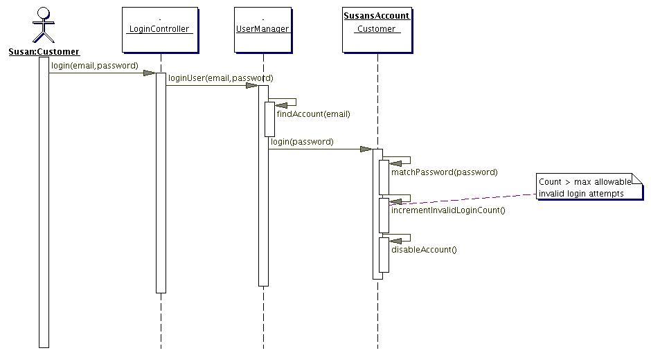
Figure 4:Unsuccessful Login: Email/Password combination invalid, failed login count > Max allowable |
|
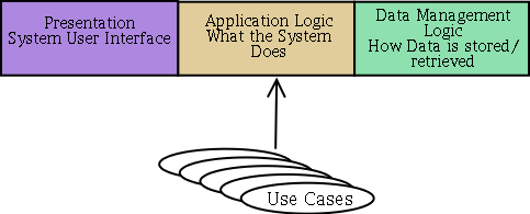
Sequence diagrams help us to understand which objects are necessary for the development of an application. It also helps us to determin which objects are domain objects and which objects are application objects. Application objects are those which are concerned with creating an application. Domain objects are those objects which are concerned with satisfying the customer's requirements. Application objects work in concert with domain objects to solve the customer's requirements within an application framework. Are Controllers application or domain objectsControllers and managers can be either application or domain, depending on the context. Specifically, if the domain contains entities that behave like controllers (eg. a catalogue of Trouble Tickets or a fleet of cars) then those controllers are part of the domain. If the domain does not contain these entities, but they are needed within the application framework, then those controllers are application objects. The first object within a sequence diagram is almost always an application Controller (although, it could be a domain controller). Application controllers can communicate directly with domain objects or they might communicate with domain controllers (which, in turn, communicate with the domain objects). It is important to note here that there are no hard-and-fast rules regarding these objects. The important thing to remember is that all of the objects involved remain cohesive. Controllers and the 3 layer modelThe purpose of Use Cases is to define what the system does. In relation to the Gartner 3-layer model, we see that Use Cases really describe the application layer. (This is why Use Cases should not include a discussion about the User interface. Similarly, Use Cases should NOT include a discussion about the Data Management either.) Figure 5 illustrates this concept.
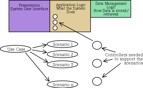
Figure 5: Application logic and Use Cases Since a Scenario is a specific walk-through of a Use Case, it is conceivable that each Use Case can generate several Scenarios (the number of scenarios generated is one form of assessing the complexity of the Use Case). Each Scenario can be represented via a Sequence Diagram. The first object within any Sequence Diagram is always a Controller object. Therefore, the high level interface of the Application Layer for a given Use Case is the public interface of the controller objects needed to support all of the Scenarios which are derived from the Use Case. Figure 6 illustrates this structure.
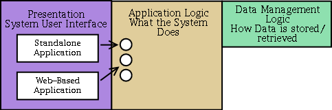
Figure 6: Controllers and the Application Layer Presentation and Application layer communicationThe presentation layer is now provided a framework which it can use to access the application functions. The application framework is not coupled to any specific presentation layer. Any presentation structure can use the application functionality as long as it couples to the application layer's high level interface. Figure 7 illustrates this structure.
Figure 7: Multiple Presentation layers using a single Application Layer. |
|
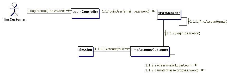
Collaboration diagrams are similar to Sequence diagrams in that they show the same information. While Sequence diagrams emphasize the sequence of events, Collaboration diagrams emphasize which objects collaborate to satisfy the scenario. Most case tools will automatically generate Collaboration diagrams from Sequence diagrams. Since Collaboration and Sequence diagrams show the same information, many people do not understand the purpose of Collaboration diagrams. The difference is really in the focus or emphasis of the diagram. Sequence diagrams use a lot of space to show the sequence of events. Most sequence diagrams do not lend themselves to added design information because they are already fairly visually complex. Collaboration diagrams, on the other hand, take up less space and are considerably less visually complex. Further design artifacts can be addded to collaboration diagrams. Figure 8 shows the Collaboration diagram from the Sequence diagram shown in Figure 2.
Figure 8: Collaboration diagram for Scenario: Successful Login |